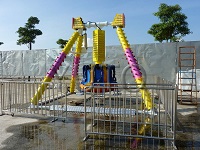
How To Do The Non-Distructive Testing Of Amusement Equipment Park Ride?
Nondestructive testing
Non-destructive testing refers to the method of inspecting and testing the specimen without damaging the specimen, also known as non-destructive testing. The definition of modern non-destructive testing is: on the premise of not destroying the test piece, by means of physical or chemical methods, with the help of modern technology and Amusement equipment, the structure, properties and states of the interior and surface of the test piece are inspected and tested. Three stages of NDT development:
The first stage, Non-distructive Inspection (NDI), detects and finds defects.
The second stage, Non-distructive Testing (NDT), not only detects and finds defects, but also detects other information about the test piece, such as structure, state, and properties.
The third stage, Non-distructiv Evaluation (NDE), not only requires the discovery of defects and the detection of the structure, state and properties of the test piece, but also requires the acquisition of more comprehensive, accurate and comprehensive information. It is supplemented by imaging technology, automation technology , computer data analysis or processing technology, etc., and the comprehensive application of materials mechanics, fracture mechanics and other disciplines. In order to make a comprehensive and accurate evaluation of the quality and performance of the test piece or product.


Conventional testing methods Conventional non-destructive testing methods include ultrasonic testing, radiographic testing, magnetic particle testing and penetrant testing.
Ultrasonic testing Ultrasonic testing is mainly used to detect internal defects of test pieces. Its application is very extensive. The so-called ultrasonic refers to sound waves with a frequency greater than 20kHz that exceed human hearing. The ultrasonic frequency used for detection is 0.4~25MHz, and the most used one is 1~5MHz.
High frequency ultrasound is used in metal detection. The reasons are as below.
(1)The directivity of the ultrasonic wave is good, and it can form a narrow beam.
(2)The wavelength is short, and small defects can also reflect well.
(3) Good distance resolution and high ability to distinguish defects.
The principle of ultrasonic testing
Ultrasonic testing can be divided into ultrasonic flaw detection and ultrasonic thickness measurement, as well as ultrasonic measurement of crystal size and stress. In ultrasonic flaw detection, there is a pulse reflection method that judges based on the echo of the defect and the echo of the bottom surface. There is a penetration method for judging the defect situation based on the shadow of the defect. There is also a resonance method for judging defects or judging plate thickness by generating standing waves from the test object. The most commonly used method is the pulse reflection method. The pulse reflection method uses longitudinal waves in vertical flaw detection, and mostly uses transverse waves in oblique incidence flaw detection. The ultrasonic wave is injected into one side of the inspected object, and then the echo reflected from the defect is received on the same side, and the defect is judged according to the echo condition. Longitudinal wave vertical flaw detection and shear wave oblique incidence flaw detection are two main flaw detection methods in ultrasonic flaw detection. Both methods have their own uses and complement each other. Longitudinal wave flaw detection is easy to find defects that are parallel or slightly inclined to the detection surface, and is mainly used for flaw detection of steel plates, forgings, and castings, while oblique-shot transverse wave flaw detection is easy to find flaws perpendicular to the detection surface or with a large inclination, and is mainly used for welding seams flaw detection.
Characteristics of ultrasonic testing
① The detection rate of area-type defects is higher, while the detection rate of volume-type defects is lower. Theoretically, the larger the defect area that reflects ultrasonic waves, the higher the echo, and the easier it is to detect. Because the area-type defects have a large reflection area and the volume-type defects have a small reflection area, the detection rate of area-type defects is high. In practice, ultrasonic testing is indeed more sensitive than radiography for the detection of cracks and unfused defects in thicker welds (above about 30 mm). But in thinner welds, this conclusion does not necessarily hold.
It must be noted that the reflected waves of area defects are not always high, some small cracks and unfused reflected waves are not high, so there are also examples of missed detection. In addition, if the reflective surface of the unfused defect in the thick weld is smooth, the single-probe inspection may not receive echoes, and it will also miss the inspection. For the detection of unfused defects in thick welds, some special ultrasonic detection techniques can be used, such as TOFD technology, tandem scanning technology, etc.
②Suitable for inspecting workpieces with larger thickness. Ultrasound has enough penetration into steel that it is not too difficult to inspect forgings up to a few meters in diameter and welds up to a hundred millimeters in thickness. In addition, when inspecting workpieces with large thicknesses, surface echoes and defect waves can be easily distinguished. Therefore, compared with radiographic testing, ultrasonic testing is more suitable for inspecting workpieces with larger thicknesses; however, ultrasonic testing is difficult for thinner workpieces, such as welds with a thickness of less than 8mm and plates with a thickness of 6mm. The detection of thin welds is difficult because the upper and lower surface shape echoes are easily confused with defect waves, which are difficult to identify. In addition, the longitudinal resolution is also affected by the presence of blind spots and the pulse width of ultrasonic flaw detection.


③ Wide application range and can be used for various test pieces.
Ultrasonic flaw detection applications include butt welds, fillet welds, T-welds, plates, pipes, bars, forgings, and composite materials. Compared with the inspection of butt welds, the inspection process of fillet welds and T-shaped welds is relatively immature, and the relevant standards are not perfect. Ultrasonic is the method of choice for the detection of internal defects in sheet, pipe, bar, forging and composite materials.
④ The detection cost is low, the speed is fast, the instrument is small in size, light in weight, and more convenient to use on site.
⑤ It is impossible to obtain an intuitive image of the defect, which is difficult to characterize, and the quantitative accuracy is not high.
Ultrasonic flaw detection obtains defect information by observing pulse echoes. The defect position is determined according to the echo position. Small defects (generally less than 10mm) can be directly measured by the wave height, and the obtained result is called the equivalent size. Large defects require moving the probe to measure, and the result is called the indicated length or indicated area. Since the defect image cannot be obtained, and the shape and surface state of the defect are also difficult to obtain, it is difficult to determine the nature of the defect. In terms of quantification, the so-called defect equivalent size, indicated size or indicated area have errors with the actual defect size, because the wave height variation is affected by many factors. The error between the size of the ultrasonic quantification of the defect and the actual size of the defect is several millimeters or even larger, which is generally considered to be normal.
In recent years, there have been some advances in ultrasonic qualitative and quantitative techniques. For example, using different scanning methods combined with dynamic waveform observation to characterize defects, using focusing probes combined with digital flaw detectors to quantify defects, and various automatic scanning, signal processing and imaging technologies, etc., but the actual application effect is not very satisfactory. .
⑥ There is no direct witness record of the test results.
Because there is no direct witness record like radiography, the authenticity, intuitiveness, comprehensiveness and traceability of ultrasonic inspection results are not comparable to that of radiography. The reliability of ultrasonic testing is largely affected by the responsibility and technical level of the testing personnel. If the inspection method is improperly selected, or the process is not properly formulated, or the operation is wrong, it may lead to the missed inspection of large defects. However, it is difficult to review or review the ultrasonic inspection results, because the wrong inspection results are not as easy to find and correct as radiography, which is a major shortcoming of ultrasonic inspection.
Although the digital ultrasonic flaw detector developed in recent years can record the waveform, it still cannot be used as a position measurement meter. Only by correlating the probe position, echo reflection point position and echo signal in the whole process of detection, can the real detection be recorded directly, which is very difficult for portable ultrasonic instruments and manual flaw detection methods. .
⑦ The positioning of the defects in the thickness direction of the workpiece is more accurate. Compared with radiography, since radiography cannot locate the defects in the thickness direction of the workpiece, the defects found by radiography are usually located by ultrasonic inspection.


⑧Material and grain size have influence on flaw detection.
Coarse-grained materials, such as cast steel, austenitic stainless steel welds, and electroslag welds that have not been normalized, are generally considered unsuitable for ultrasonic flaw detection. This is because the grain boundaries of the coarse grains will reflect sound waves, and a large number of “grass echoes” will appear on the screen, which are easily confused with defect waves, thus affecting the detection reliability. In recent years, special research has been carried out on the ultrasonic flaw detection technology of austenitic stainless steel welds. If a special probe (longitudinal wave narrow pulse probe) is used to reduce the signal-to-noise ratio and a special process is developed, ultrasonic testing of austenitic stainless steel welds can be implemented. Its accuracy and reliability are basically guaranteed.
⑨ The irregular shape and some structures of the workpiece will affect the detection.
For example, forgings with more tables, grooves and holes, welds with different thicknesses, butt welds between tube sheets and cylinders, girth welds connecting heads with shorter straight sides and cylinders, high-neck flanges Butt welds, etc. to the pipe can make inspection difficult.
⑩ Uneven or rough surfaces will affect coupling and scanning.
The flatness and roughness of the probe scanning surface have a certain influence on ultrasonic testing. Generally, the rolled surface or the machined surface can meet the requirements, and the severely corroded surface and the original cast and forged surface cannot be tested. Special attention should be paid to the flatness of the surface polished with the grinding wheel to prevent the generation of grooves and pits, otherwise the coupling and detection will be seriously affected.



X-ray detection There are many types of rays, among which X-rays, γ-rays and neutron rays are easy to penetrate materials. All three types of rays are used for non-destructive testing, and neutron rays are only used for some special occasions.
The main application of radiographic inspection is to detect macroscopic aggregate defects inside the test piece. According to different special line detection, it is divided into many different methods.
Radiography is a non-destructive testing method that uses X-rays or γ-rays to penetrate the test piece and uses film as the recorded information. This method is the most basic and most widely used radiographic testing method.
The principle of radiography: X-rays and γ-rays are electromagnetic waves with extremely short wavelengths. From the point of view of wave-particle duality in modern physics, it can also be regarded as a very high-energy photon beam.
The important property of the ray is to make the film photosensitive. When X-ray or γ-ray irradiates the film, like ordinary light, it can make the silver halide in the emulsion layer of the film produce a latent image center, which will be blackened after development and fixing, and receive rays The more parts, the higher the degree of blackening, this effect is called radiography. Because X-rays or gamma rays make silver halide much less sensitive than normal light, special X-ray films must be used, which are coated with thicker latex on both sides. In addition, an intensifying screen that can enhance the photosensitive effect is also used, and the intensifying screen is usually made of lead foil.
If there are defects in the material, it will affect the absorption of radiation and change the intensity of the transmitted radiation, which can be measured with film. Perform radiographic inspection on the workpiece. When there is a defect with a thickness of ΔT in an object with a thickness of T, the exposed film is developed, fixed, washed and dried in a dark room, and then the negative film is placed on the viewing lamp for observation. , According to the image formed by the change of blackness on the negative, it can be judged whether there is a defect, and the type, quantity and size of the defect. 2) Radiographic testing equipment: Radiographic equipment can be divided into three categories: X-ray flaw detectors, high-energy ray flaw detectors (including high-energy linear accelerators, electron cyclotrons) and γ-ray flaw detectors. The tube voltage of the X-ray flaw detector is below 450kV. The energy of the high-energy accelerator is 1~24MeV, while the ray energy of the γ-ray flaw detector depends on the radioisotope.



①X-ray flaw detector.
X-ray flaw detectors can be divided into two types: portable and mobile. The mobile X-ray flaw detector is used for radiographic flaw detection in the transillumination room. The mobile X-ray flaw detector has high tube voltage and tube current, and the maximum penetration thickness can reach 100mm. Its high pressure generating device, cooling device and game machine head are installed independently. The portable X-ray flaw detector is mainly used for on-site radiography, the tube voltage is generally less than 320kV, and the maximum penetration thickness is about 50mm. The main components of the X-ray flaw detector include four parts: the nose, the high-voltage generating device, the power supply and control system, and the cooling and protection facilities.
②High-energy ray flaw detection equipment.
In order to meet the requirements of X-ray inspection of large thickness workpieces, since the 1940s, various high-energy X-ray inspection devices have been designed and manufactured to expand the thickness of X-ray inspection of steel parts to 500mm. They are linear accelerators and electron cyclotrons. Among them, linear accelerators can generate large doses of rays, with high efficiency and large transillumination thickness, and are currently the most widely used.
③ γ-ray flaw detector.
Gamma ray flaw detector has become an important and widely used equipment for ray flaw detection due to its small size of ray source and no need for power supply. The gamma ray flaw detector consists of four parts: ray source, source container, operating mechanism, support and moving mechanism.


③ γ-ray flaw detector.
Due to the small size of the ray source, the γ-ray flaw detector does not require a power supply, and can work in narrow sites, high altitudes and underwater. Panoramic exposure possible. It has become an important and widely used equipment for radiographic inspection. The gamma ray flaw detector consists of four parts: ray source, source container, operating mechanism, support and moving mechanism.
Radiation safety protection:
①Hazards of rays: rays have biological effects, and excessive radiation doses may cause radiation damage and destroy normal human tissues. Radiation has a cumulative effect, and exposure to excessive radiation doses is one of the carcinogenic factors, and may affect the next generation, resulting in deformities and stunting of infants.
② Radiation protection method: Radiation protection refers to taking various measures under the conditions as possible, while ensuring the completion of the radiographic inspection task, the dose equivalent received by the operator does not exceed the limit value, and the operator and other personnel are reduced as much as possible. absorbed dose.
The main protection measures are shielding protection, distance protection and time protection.
(1) Shielding protection is a method of adding effective and reasonable shielding objects between the radiation source and the operator and other nearby personnel to reduce radiation.
(2) Distance protection is to achieve the purpose of protection by increasing the distance between the radiation source and the operator when there is no shield or the thickness of the shield is insufficient;
(3) Time protection is to reduce the time that the operator is in contact with the radiation to reduce radiation damage. This is because the amount of radiation absorbed by the human body is proportional to the time when the person is exposed to the radiation.
The above three protection methods have their own advantages and disadvantages. In actual flaw detection, they can be selected according to the conditions at that time. In order to get better results, three protection methods are often used at the same time.
4) Features of radiography
① The results of radiographic inspection are directly recorded on the negative film. Because the information recorded on the negative film is very rich and can be stored for a long time, radiography has become the most authentic, most intuitive, most comprehensive and reliable record among various nondestructive testing methods. The best traceability detection method.
②The projection image of the defect can be obtained, and the defect is accurate qualitatively and quantitatively. Among the various nondestructive testing methods, radiography is the most accurate for qualitative determination of defects. In terms of quantification, the determination of the length and width of volumetric defects (porosity, slag inclusion defects) is also very accurate, and the error is roughly a few tenths of a millimeter. However, for area defects (such as cracks and unfused defects), if the size of the end of the defect (height and opening width) is small, the extension of the affected tip on the negative film may be unclear, and the quantitative data will be small.
③ The detection rate of volume defects is very high.
The detection rate of area defects is affected by many factors. Volume defects refer to pores and slag inclusions. Under normal circumstances, radiography can roughly detect volumetric defects whose diameter is more than 1% of the thickness of the workpiece, but for thin workpieces, limited by the resolution of the human eye, the minimum size of defects that can be detected is about 0.5mm. Area defects refer to cracks and unfused defects. The factors affecting the detection rate include defect shape and size, suitable illumination, illumination angle, transillumination geometric conditions, source and film type, etc. Since thick workpieces affect the display of details, it is generally said that the crack detection rate in thick specimens is low, but for thin specimens, unless the height and opening of cracks or unfusions are extremely small, as long as the camera angle is appropriate, the sensitivity of the film is in line with requirements, the crack detection rate is still high enough.
④ It is suitable for testing thinner workpieces but not for thicker workpieces.
Because inspection of thick workpieces requires high-energy radiation damage equipment. The transillumination thickness of 300kV portable X-ray flaw detector is generally less than 40mm, and the thickness of 420kV mobile X-ray flaw detector and Ir192γ-ray transillumination are both less than 100mm. It is difficult to use an accelerator or Co60 to photograph workpieces with a thickness greater than 100mm. In addition, as the thickness of the plate increases, the absolute sensitivity of radiography decreases, that is to say, when using radiography for thick workpieces, the possibility of missed detection of small size defects and some area defects increases.
⑤ It is suitable for detecting butt welds, but the effect of detecting fillet welds is poor, and it is not suitable for detecting plates, bars and forgings. When the fillet weld is detected by radiography, it is difficult to arrange the transillumination, and the blackness of the photographed film varies greatly, and the imaging quality is not good enough. The reason why radiography is not suitable for inspecting plates, bars, and forgings is that most of the defects in the plates and forgings are parallel to the plate, that is, perpendicular to the beam, so radiography cannot be detected. In addition, the thickness of bars and forgings is relatively large, and the penetration of rays is difficult, and the effect is not good.
⑥ Some specimen structures and site conditions are not suitable for radiography. This is because when the penetration method is used for inspection, the inspection equipment needs to be close to both sides of the workpiece, and sometimes the structure and site conditions will limit the inspection.
⑦ It is difficult to determine the position and size (height) of the defect in the thickness direction of the workpiece. Except for some root defects that can be combined with welding knowledge and rules to determine their position in the thickness direction of the workpiece, most defects cannot be located with the information provided by the negative film. The defect height can be judged by the blackness comparison method, but the accuracy is not high, especially for small cracks in the image, the blackness cannot be accurately measured, and the error of measuring the defect height by the blackness comparison method is large.


.jpg)
⑧ Radiographic detection speed is slow. Under normal circumstances, the length of a directional X-ray flaw detector does not exceed 300mm in one transillumination, and it takes 10 minutes to take a film, and the exposure time of the γ-ray source is generally longer. Typically, radiography takes several hours from the start of transillumination to the assessment of results, and compared to other nondestructive testing methods, radiography is slow and inefficient. Except for special occasions, such as circumferential X-ray flaw detector circumferential exposure or y-ray source panoramic exposure technology application can greatly improve the detection efficiency.
⑨ rays are harmful to the human body. Radiation can cause many kinds of damage to human tissue, so the dose equivalent limit is specified for occupational radioactive workers. It is required that the dose equivalent received by the operator does not exceed the limit value while ensuring the completion of the radiographic inspection task, and the absorbed dose of the operator and other personnel should be reduced as much as possible. On-site photography will bring some problems to the construction organization due to protection, especially gamma rays, and strict management regulations on radioisotopes will affect work efficiency and cost.


Magnetic particle inspection
1) The principle of magnetic particle inspection: After the ferromagnetic material is magnetized, a strong magnetic induction intensity is generated inside, and the magnetic line density increases hundreds to thousands of times. If there are discontinuities in the material (including discontinuities caused by defects) and the discontinuity caused by the structure, shape, material, etc.), the magnetic field lines will be distorted, and some of the magnetic field lines may escape the surface of the material and pass through the space to form a leakage magnetic field. The local magnetic pole of the leakage magnetic field can attract ferromagnetic substances,


The discontinuity caused by the crack in the test piece distorts the magnetic field lines, because the permeability of the air medium in the crack is much lower than that of the test piece. The magnetic lines of force are blocked, some of the magnetic lines of force are squeezed to the bottom of the defect, some pass through the cracks, and some are pushed out of the surface of the workpiece and then enter the workpiece. If magnetic powder is sprinkled on the surface of the workpiece at this time, the leakage magnetic field will attract the magnetic powder, forming a magnetic powder accumulation similar to the shape of the defect. We call this a magnetic trace, which shows a defect. When the crack direction is parallel to the propagation direction of the magnetic field lines, the propagation of the magnetic field lines will not be affected, and the defect cannot be detected at this time.
Factors affecting the leakage magnetic field.
The greater the strength of the external magnetic field, the greater the strength of the leakage magnetic field formed. Under a certain external magnetic field strength, the higher the magnetic permeability of the material, the easier the workpiece is to be magnetized, the greater the magnetic induction strength of the material, and the greater the leakage magnetic field strength.
When the extension direction of the defect forms an angle of 90° with the direction of the magnetic field lines, the leakage magnetic field strength is also the largest because the defect blocks the largest area of the magnetic field lines passing through. As the direction of the defect and the direction of the magnetic field line gradually decrease (or increase) from 90°, the strength of the leakage magnetic field decreases significantly. Therefore, during magnetic particle inspection, it is usually necessary to perform magnetization in two (the directions of the two magnetic lines of force are perpendicular to each other) or in multiple directions.
As the burial depth of the defect increases, the magnetic field lines overflowing the surface of the workpiece decrease rapidly. The greater the burial depth of the defect, the smaller the leakage magnetic field. Therefore, magnetic particle inspection can only detect cracks and other defects on or near the surface of workpieces made of ferromagnetic materials.



Magnetic particle testing equipment and equipment.
Magnetic particle testing equipment and equipment are magnetic flaw detectors and materials such as sensitivity test pieces, magnetic powders and magnetic suspensions that are used together with them.
①Magnetic flaw detector.
Magnetic flaw detectors can be divided into three types: fixed, mobile and portable according to the size and weight of the equipment. Portable flaw detectors are small in size and light in weight; they are suitable for field and high-altitude operations, and are mostly used for local flaw detection of welds and large workpieces. Electromagnetic yoke flaw detectors are the most commonly used.
The electromagnetic yoke flaw detector is a U-shaped iron core wound with a coil. If a current passes through the coil, a large number of magnetic lines of force are generated in the iron core. The yoke is placed on the workpiece, and the workpiece between the two poles is partially magnetized. The two poles of the yoke can be made into movable type. Yes, the pole spacing and angle are adjustable, and the magnetization index is the weight of the iron block that the yoke can pick up (called the lifting force). The standard requirements are: when using the maximum spacing of the yokes, the lifting force of the AC electromagnetic yoke is at least 45N, the lifting force of the DC electromagnetic yoke is at least 177N, and the lifting force of the cross yoke is at least 118N.
②Sensitivity test piece. The sensitivity test piece is used to check the comprehensive performance of magnetic particle inspection equipment, magnetic powder and magnetic suspension. Sensitivity test strips are usually made of thin iron sheets with straight and circular grooves engraved on one side to a certain depth. Standard test pieces are A1 type, C type, D type and M1 type. The commonly used A1 type test piece is made of soft magnetic material with a thickness of 100μm or 50μm. Generally, the A1-30/100 type standard test piece is used. The meaning of the numbers is: the numerator represents the groove depth of 30μm, and the denominator represents the thickness of the slice. 100um.
When using, the side of the test piece engraved with the artificial groove is closely attached to the surface of the workpiece to be inspected; then the workpiece is magnetized and magnetic powder is applied. The corresponding slots are clearly displayed.
③ Magnetic powder and magnetic suspension. Magnetic powder is ferric oxide or ferric oxide powder with high magnetic permeability and low remanence. According to the added dye, magnetic powder can be divided into fluorescent magnetic powder and non-fluorescent magnetic powder. Non-fluorescent magnetic powder has several colors of black, red and white. Since the display contrast of fluorescent magnetic powder is much higher than that of non-fluorescent magnetic powder, the detection by fluorescent magnetic powder has the advantages of easy magnetic trace observation, fast detection speed and high sensitivity. However, fluorescent magnetic particle detection requires some additional conditions, such as dark environment and black light.



The characteristics of magnetic particle testing.
① It is suitable for the detection of ferromagnetic materials, and cannot be used for the detection of non-ferromagnetic materials.
Among the materials used for the manufacture of special equipment, ferromagnetic materials include various carbon steels, low alloy steels, martensitic stainless steels, ferritic stainless steels, nickel and nickel alloys, etc. Materials that do not have ferromagnetic properties include austenitic steels. Stainless steel, titanium and titanium alloys, aluminum and aluminum alloys, copper and copper alloys, etc.
② It can detect surface and near-surface defects, and cannot be used to inspect internal defects.
The detectable defect burial depth is related to the condition of the workpiece and the process conditions. For smooth surfaces, such as the ground shaft, the near-surface defects with a depth of 1~2mm can generally be detected, and a strong DC magnetic field can be used to detect the depth of up to 2mm. 3~5mm near-surface defects. However, for weld inspection, because the surface is rough and uneven, the background noise is high, and weak signals are difficult to identify, the probability of missed detection of near-surface defects is high.
③The detection sensitivity is very high, and extremely small cracks and other defects can be found. Relevant theoretical research and test results believe that the minimum crack size that can be detected by magnetic particle testing is 1 μm in width, 10 μm in depth, and 1 mm in length, but the crack size that can be detected in actual field applications cannot reach this level, which is higher than the above-mentioned level. The value is much larger.
④The detection cost is very low and the speed is very fast.
⑤ The shape and size of the workpiece have an influence on the flaw detection, and sometimes it cannot be detected because it is difficult to magnetize. There are many magnetization methods for magnetic particle inspection. According to the requirements of the shape, size and magnetization direction of the workpiece, selecting the appropriate magnetization method is an important part of the magnetic particle inspection process. If the magnetization method is not selected properly, it may lead to detection failure. For some structures that are not conducive to magnetization, the magnetization conditions can be improved by connecting auxiliary blocks to lengthen or form a closed loop. For structures that do not have a suitable magnetization method and cannot improve the magnetization conditions, other detection methods should be considered.
Penetration testing
The principle of penetration testing.
After the surface of the part is applied with the permeate containing fluorescent dyes or coloring dyes, under the action of the capillary, the permeate can penetrate into the defects of the surface opening after a certain period of time.
After removing the excess penetrant on the surface of the part, apply the developer on the surface of the part. Similarly, under the action of the capillary, the developer will attract the penetrant remaining in the defect, and the penetrant will seep back into the developer.
Under a certain light source (ultraviolet light or white light), the traces of the permeate at the defect are displayed (yellow-green fluorescence or bright red), so as to detect the shape and distribution of the defect.
Penetration testing operations have four basic steps: penetration, cleaning, imaging, and observation. In the specific operation, in addition to the above basic steps, it is possible to add other processes. For example, sometimes pretreatment is required to facilitate penetration; when certain types of imaging agents are used, drying treatment is required; Wash off and emulsify some permeates.


Classification of penetration testing.
According to the dye components contained in the penetrant, penetrant testing can be divided into two categories: fluorescence method and coloring method; according to the penetrant removal method, penetrant testing can be divided into three categories: washing type, post-emulsification type and solvent removal type. And its imaging methods include wet imaging, quick-drying imaging, dry imaging and developer-free imaging.
Characteristics of penetration testing.
① Penetrant testing can be used to detect any kind of material except loose porous materials. Among engineering materials, there are very few loose porous materials, and most materials, including ferrous metals, non-ferrous metals, ceramic materials and plastics, are non-porous materials, so the adaptability of penetrant testing to pressure-bearing special equipment materials is the most extensive. of. However, considering the method characteristics, cost, efficiency and other factors, magnetic particle testing is generally preferred for ferromagnetic material workpieces, and penetrant testing is only an alternative method. However, for non-ferromagnetic materials, penetrant inspection is the preferred method for surface defect detection.
② Parts with complex shapes can also be tested by penetration, and a comprehensive test can be achieved in one operation. The workpiece geometry has a great influence on magnetic particle inspection, but has little effect on penetrant inspection. For workpieces that are not conducive to magnetization due to their structure, shape, and size, penetrant testing can be considered instead of magnetic particle testing.
③If there are defects in several directions at the same time, the detection can be completed in one operation. In order to ensure that defects are not missed, magnetic particle inspection requires magnetization inspection in at least two directions, while penetrant inspection requires only one inspection operation.
④ No large equipment is required, and no water or electricity is required. For sites without water, power or high-altitude work, it is very convenient to use portable spray cans to color penetrant detection agents.
⑤ The surface roughness of the workpiece has a great influence, and the detection results are often easily affected by the level of the operator. The high surface roughness of the workpiece will lead to a high background, which affects defect recognition, so the lower the surface roughness, the better the penetration detection effect. Since penetration testing is a manual operation, there are many testing procedures, and if the operation is not performed properly, it will cause missed testing.
⑥ Defects with surface openings can be detected, but buried defects or closed surface defects cannot be detected. It can be seen from the principle of penetrant detection that the penetrant penetrates into the defect and can be retained after cleaning to produce defect display. The larger the defect space, the more penetrant retained, and the higher the detection rate. Buried defects cannot penetrate the permeate, and closed surface defects have no space for permeate, so they cannot be detected.
⑦ There are many testing procedures and the speed is slow. Penetrant testing includes at least the following steps: pre-cleaning, infiltration, removal, imaging, and observation. Even for small workpieces, it takes 20-30 minutes to complete the entire process. It is very troublesome to detect large-area penetration of large workpieces, and each process, including pre-cleaning, penetration, removal, and development, takes time.
⑧ The detection sensitivity is lower than that of magnetic particle detection. From the effect evaluation of practical application, the sensitivity of penetrant detection is much lower than that of magnetic particle detection, and the size of detectable defects is 3 to 5 times larger. Even so, the sensitivity of penetrant testing is high, at least an order of magnitude higher, than radiographic or ultrasonic testing.
⑨ The material is more expensive and the cost is higher. Due to the many testing procedures, the speed is slow, and the labor cost is also high.
⑩ Most of the detection agents used in penetration testing are flammable and toxic, and effective measures must be taken to ensure safety. To ensure safe operation, adequate attention must be paid to workplace ventilation, as well as eye and skin protection.


