How Does The Chain Drive Of The Amusement Equipment Work
Chain drive
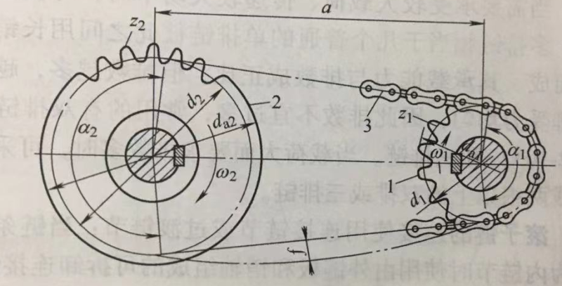
Chain drive and its transmission ratio. A chain drive is a transmission that transmits motion and (or) power consisting of a chain and a sprocket with a special tooth profile. It is a meshing transmission with an intermediate flexible member (chain). As shown in Figure 2-102, when the driving sprocket 1 rotates, the driven sprocket 2 is rotated by the meshing force between the chain 3 and the two sprockets, thereby realizing the transmission of motion and (or) power.
Common types of chain drives. There are many types of chain drives, as shown in Figure 2-103, the most commonly used are roller chains and toothed chains.
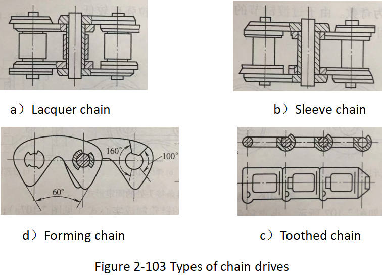
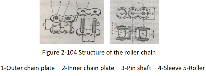
Figure 2-104 shows a roller chain (sleeve roller chain), which consists of an outer chain plate, an inner chain plate, a pin, a sleeve and a roller.
The pin shaft and the outer chain plate, the sleeve and the inner chain plate are respectively connected by interference fit to form the outer chain link and the inner chain link. ), when the chain is flexed and extended, the inner and outer links can rotate relative to each other. The rollers are mounted on the sleeve and can rotate freely.
When the chain meshes with the sprocket, the rollers and the sprocket teeth roll relative to each other, and the rolling friction between the two is mainly, which reduces the chain and the sprocket teeth from the surface. of wear.Application range:amusement park、playground、theme park.
When it is necessary to withstand larger loads and transmit larger power, multi-strand chains can be used.
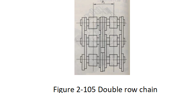
The multi-row chain is equivalent to several ordinary single-row chains connected with each other with long pins. Its carrying capacity is proportional to the number of rows, but the more rows there are, the more difficult it is to make each row bear even force, so the number of rows should not be too many.
The commonly used double-row chains (see Figure 2-105) and three-row chains are. When the load is large and the number of rows is required, two or more double-row or triple-row chains can be used.
The connection of the upper roller chain uses connecting links or transition links:
when both ends of the chain are inner links, use a detachable connecting link consisting of an outer link plate and a pin, with a split pin (wire lock pin) or The elastic locking plate is connected (see Figure 2-106a, b), and the number of links of the chain after connection is even.
When one end of the chain is an inner link and the other end is an outer link, use a transition link to connect (see Figure 2-106c), and the number of links in the chain after connection is an odd number. Due to the low tensile strength of the transition link, it should be avoided as much as possible.

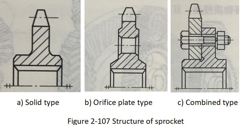
The structure of the sprocket is shown in Figure 2-107. Small-diameter sprockets can be made into solid type (see Figure 2-107a); medium-diameter sprockets can be made into orifice type (see Figure 2-107b); large-diameter sprockets can be combined (see Figure 2-107c) ).
Application characteristics of chain drive In chain drive, the forward speed and the up and down jitter speed of the chain change periodically.
When the driving sprocket rotates at a constant speed, the angular velocity of the driven sprocket and the instantaneous transmission ratio of the chain drive change periodically, so the chain drive is not suitable for occasions that require high motion accuracy.
The non-uniformity of the chain drive is caused by the fact that the chain around the sprocket forms a regular polygon, so it is called the polygon effect of the chain drive.
The higher the speed of the sprocket, the larger the pitch, and the smaller the number of teeth, the greater the dynamic load of the transmission. The relative velocity of the chain link and sprocket at the moment of engagement will also cause shock and dynamic loads. The larger the chain pitch and the higher the speed of the sprocket, the stronger the shock.
