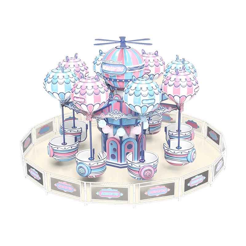
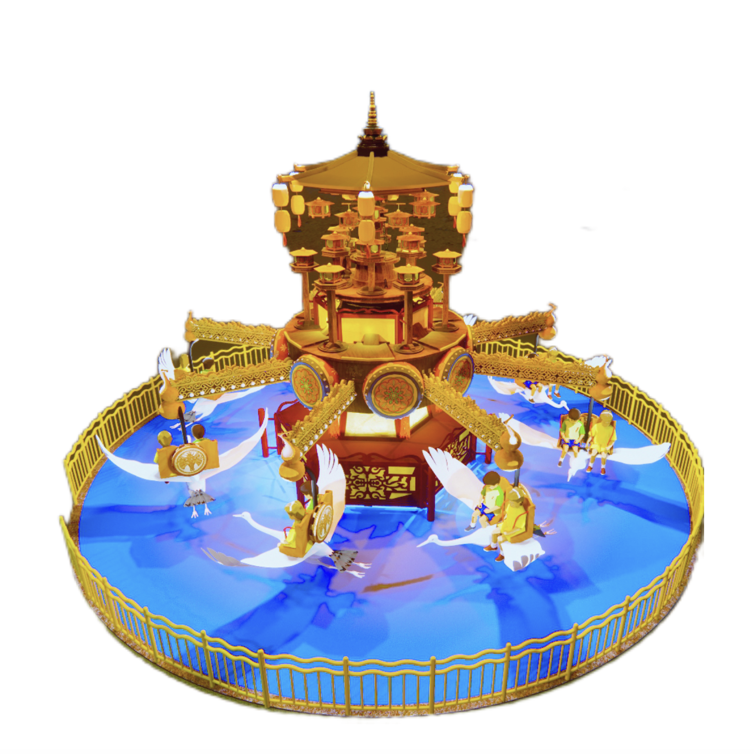
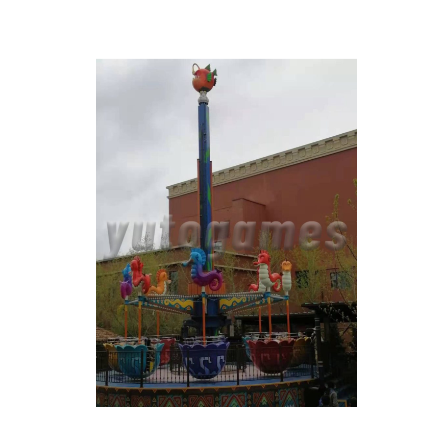
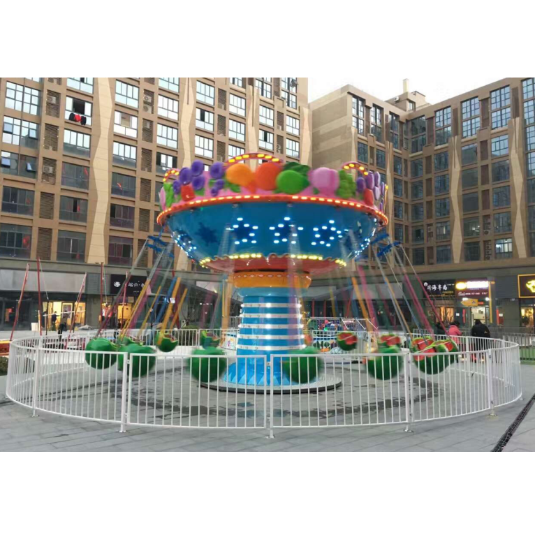
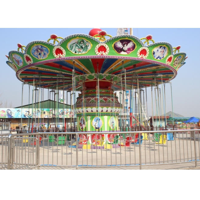
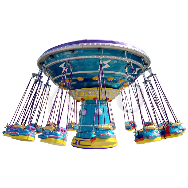
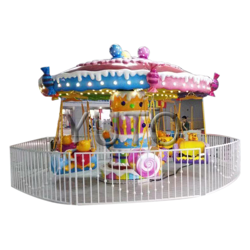
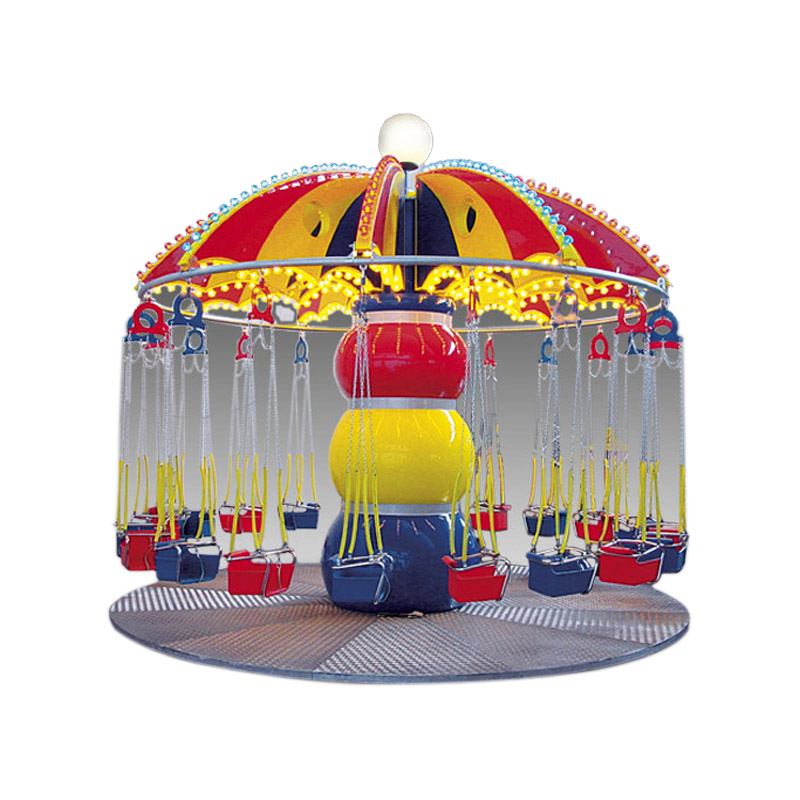
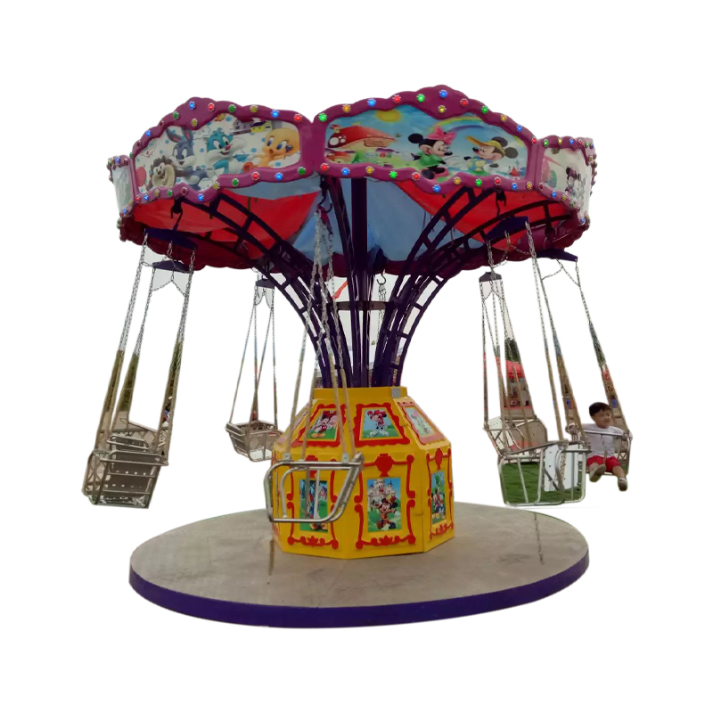
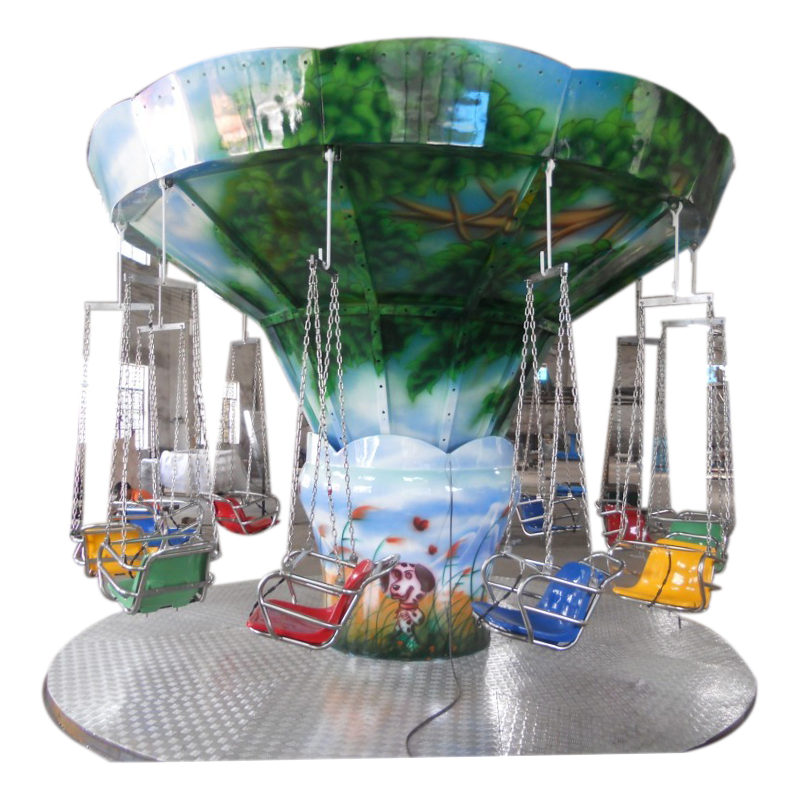
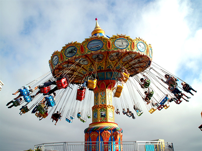
Flying Chair Ride
What characteristic is there the structure type and movement form of rocking head flying chair ?
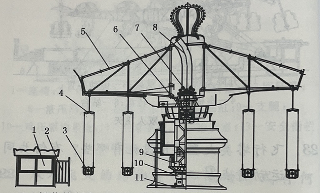
1.Operation control room;2.Safety fence;3.Seat;4.Hanging assembly;5.Rotating parachute stand;6.Hydraulic lifting device;7.Guided taxiing frame;8.Guide curved rail ;9.Rack;10.Transmission mechanism;11.Base
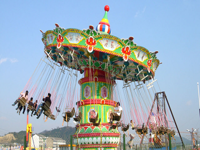
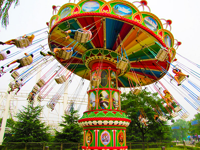
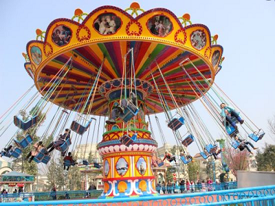
The flying chair ride is a typical product of spinning fair rides in large type of amusement facilities.
It is characterized by hanging the seat on the Rotating parachute stand with flexible parts, rotating the tower through the transmission mechanism, and at the same time, the hydraulic lifting device makes the whole cockpit of the parachute rise and fall, as well as change the inclination movement, and rise and fall back and forth.
Tourists are flying in the sky like a parachute, thrilling and soul-stirring. Coupled with the flight appearance and sound that attract tourists, it is a kind of flight tower amusement project which is more exciting and suitable for teenagers.
The flying chair ride is mainly composed of base frame, Revolving transmission device, rotation transmission device, hydraulic lifting system, electrical control system, as well as rack, connecting cylinder, column, bracket, turntable, seat, safety protection device, luxury fiberglass cover and so on. The schematic diagram of the structure is shown in the diagram.
Common faults of swivel flying chairs
It is best for tourists to find out whether the equipment is affixed with a safety inspection mark before riding, and keep it.
If the equipment is within the validity period of the safety inspection, it is necessary to resolutely refuse to ride without safety inspection.
Amusement equipment that has not been inspected or expired.
Difficult to start
The bearing is too tight.
Such failures generally occur in the case of new rotating flying chairs. It can be adjusted with a wrench, and the tightness is moderate. In addition, lubricating oil can be added for better effect.
The voltage is unstable or too low.
Many devices have difficulty in starting or cannot be started because the voltage is unstable or too low, mainly because the nearby voltage load is too large. This phenomenon is especially obvious in summer.
The way to check is to press the start button of the electric control cabinet and observe whether the voltmeter is normal. The solution is to replace the power cord with a larger square number or replace the line access point.
The V-belt is loose.
If the V-belt is loose, you can adjust the distance between the motor and the pulley or replace it with a new V-belt of the same type.
1.Rotary flying chair series
There are many products in the swivel flying chair series, such as aerial flying chairs, hurricane flying chairs, etc. Among them, the hurricane flying chair is a large-scale flying tower amusement machine that integrates various forms of movement such as rotation, lift, and variable inclination. After the Hurricane Flying Chair is powered on, the tower body will slowly rises when the umbrella-shaped turntable and the middle turntable rotate in dislocation. At the same time, the turntable shakes, and the flying chair is rippling. Tourists are like flying and floating in the air, that is very exciting.
(1)The main structure.the Hurricane Flying Chair consists of base frame, revolution transmission device, autorotation transmission device, hydraulic lifting system, electrical control system, frame, coupling cylinder, column, bracket, turntable, seat, safety protection device and luxury glass fiber reinforced plastic cover and so on.
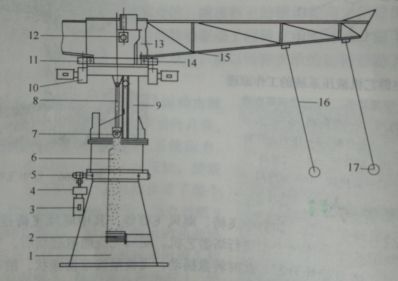
Structure of the Hurricane Flying Chair
1-Frame 2-Current collector 3-Electric motor 4-Reducer, Bearing, Pinion 5-External gear slewing support 6—Connecting cylinder 7-Plain bearing housing assembly 8-Hydraulic cylinder 9-Column assembly 10-Geared motor 11-Small shaft, bearing, pinion 12-Roller Frame Assembly 13-Support, turn 14-Slewing support 15-Turntable 16—Sling 17—Seat
1) Base frame and transmission part.The base is the basic part of the equipment. It adopts a tube-mounted web reinforced structure. The upper end is a turntable that rotates counterclockwise. It is used to install and support the upper structure and rotate with the turntable. Its interior conducts electricity for the slip ring, which powers the upper rotating part. It drives the pinion through the deceleration motor, and then the pinion drives the slewing bearing to rotate, as shown in Figure 3-373.This transmission also can be realized in the following ways. The motor drives the worm reducer through the belt transmission, drives the pinion, and drives the slewing mechanism to rotate.
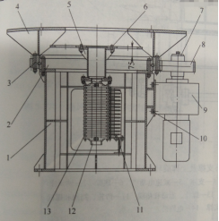
Transmission mechanism at the bottom of the Hurricane Flying Chair
1-Support ,2-Slewing support ,3-Bolts Nuts and Washers ,4-tray ,5-Connection board,6-retaining ring,7-Gear, 8-Geared motor ,9-Bolts and Washers, 10- Brush device, 11-Support tube ,12-Slip ring group
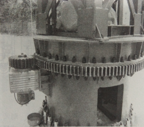
Gear transmission at the bottom of the Hurricane Flying Chair
2)Support system and guide wheel transmission part.They are the support and motion guide parts of the upper moving structure to ensure the relative position of the relevant parts and support the safe operation of the upper equipment. The built-in hydraulic lifting system provides power for the lifting and lowering of the turntable.
The lifting and lowering of the entire tower body is realized by the built-in hydraulic lifting system, and the guide mechanism is lifted along the guide rail through the hydraulic cylinder to realize the lifting movement. The rotation of the top of the tower is achieved by the two deceleration motors 5 obtaining power through the large collector ring group 2 to synchronously drive the pinion to drive the slewing bearing to rotate, thereby also realizing the rotation of the top of the tower.
The rotation of the top of the tower also can be realized by the inner slewing bearing, that is, the motor is fixed on the guide sliding system, and the pinion is driven by the conduction of the collector ring to drive the inner slewing bearing to rotate, so as to realize the rotation of the top of the tower.
The structure of the upper and lower guide groups of the Hurricane Flying Chair
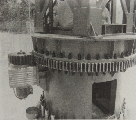
Gear transmission at the bottom of the Hurricane Flying Chair
2)Support system and guide wheel transmission part.They are the support and motion guide parts of the upper moving structure to ensure the relative position of the relevant parts and support the safe operation of the upper equipment. The built-in hydraulic lifting system provides power for the lifting and lowering of the turntable. The lifting and lowering of the entire tower body is realized by the built-in hydraulic lifting system, and the guide mechanism is lifted along the guide rail through the hydraulic cylinder to realize the lifting movement.
The rotation of the top of the tower is achieved by the two deceleration motors 5 obtaining power through the large collector ring group 2 to synchronously drive the pinion to drive the slewing bearing to rotate, thereby also realizing the rotation of the top of the tower. The rotation of the top of the tower also can be realized by the inner slewing bearing, that is, the motor is fixed on the guide sliding system, and the pinion is driven by the conduction of the collector ring to drive the inner slewing bearing to rotate, so as to realize the rotation of the top of the tower.
The structure of the upper and lower guide groups of the Hurricane Flying Chair, and its function is to guide and slide along the track on all sides.
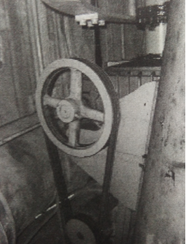
Hurricane Flying Chair Bottom belt drive

Hurricane Flying Chair Support and Upper Swivel System
1-Guide wheel set 2-Large slip ring group 3-Support ring 4-support 5-Geared motor 6-Bottom beam 7-Bearing housing 8-Pins, Retaining Rings and Cotter Pins 9—Outrigger 10—Bolts, Nuts and Washers 11—Gears, Rings and Bolts 12—lewing support 14—Brush device
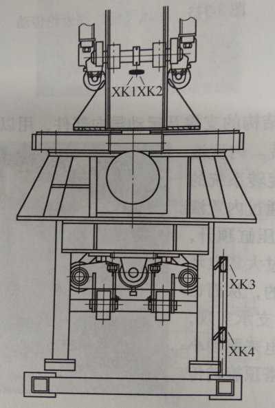
Hurricane Flying Chair Support and Upper Swivel System
XK1、XK2、XK3、XK4-XK1, XK2, XK3, XK4-travel limit switch
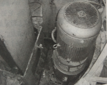
Hurricane Flying Chair Tower Top Rotation Transmission Mechanism
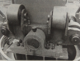
Structure of the guide group under the Hurricane Flying Chair
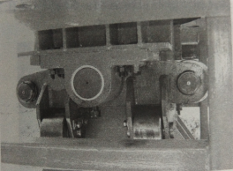
Structure of the steering group on the Hurricane Flying Chair
3)Suspension system for umbrellas and hanging chairs.The rotating umbrella skeleton is a metal structure, and its function is to support the rapid rotation of the upper rotating mechanism. The seats are suspended on different radii of the bottom surface of the disk, and they undulate and swirl with the movement of the disk. The seat is equipped with a reliable suspension and safety system to ensure the safety of passengers.
There are many ways to hang the pendant, and there are two common ones:
The first way is to weld the upper end connecting lugs on the truss of the plate body, and there are two chains to protect the middle suspension rod, preventing the suspension rod from breaking and effectively protecting the lower triangular hanging piece. Two loop chains are hung at each end of the triangle pendant, and a steel wire rope secondary protection chain is added at the connection between the loop chain and the tripod to prevent the chain from breaking and causing the seat to be unbalanced. The lower ends of the chain are respectively suspended around the seats. The seat is made of metal tube with reliable structure. There is also a cross bar on the front of the seat. When the passenger sits firmly, hang a chain with one end connected to the metal structure of the seat on the cross bar to protect the passenger from accidentally falling out when the equipment is running.
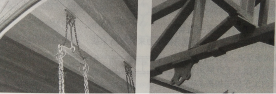
Hurricane Flying Chair Seat Hanging Upper Connection and Lifting Ear Structure, and Connection of Lifting Ear and Truss

Secondary protection of hanging chain, hanging seat and protective cross bar
The upper part of the metal boom is connected by a biaxial connection, and the secondary protection of the boom is made of steel wire rope. The upper end of the steel wire rope is directly connected to the truss structure, and the lower end is connected to the triangle. on the two pins in the middle of the frame.Each of the two pin shafts is also connected with two loop chains, which serve as the secondary protection of the seat hanging loop chain. This connection is a bit more reliable than the first.
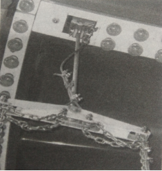
Upper connection of seat suspension system
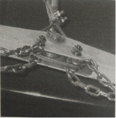
Tripod structure and secondary protection connection
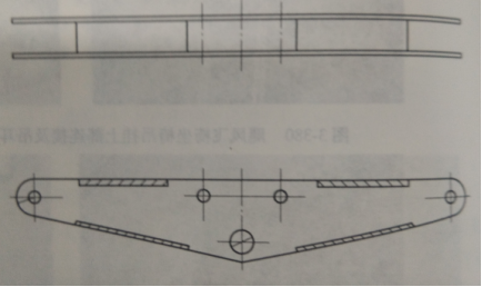
The structure of the suspension tripod of the Hurricane Flying Chair
(2)Working principle.The operation process of the Hurricane Flying Chair is as follows: after the passengers are seated, the operator presses the power switch, the equipment is powered on, and the motor drives the turntable to run. When the umbrella-shaped turntable and the middle turntable are dislocated and rotated, the tower body slowly rises, the turntable shakes at this time, the flying chairs are rippling, and the tourists seem to be flying and floating in the air. Hurricane Flying Chair is a game combining rotation and up and down motions. The mechanical and electrical control principles for these two movements are described below.
1)Mechanical transmission principle:The revolution of the turntable is realized by the revolution motor fixed on the frame. The rotation of the revolution motor drives the rotation of the worm reducer, the roller chain coupling, the transition shaft, the pinion and the external tooth slewing support through the V-belt drive, so as to realize the revolution movement of the coupling cylinder, the column and the bracket.The rotation motor fixed on the bracket drives the pinion gear and the large slewing support gear to rotate through the gear reducer to complete the rotation of the drum and the turntable. Relying on the hanging hydraulic cylinder fixed under the column chassis, the bracket, the drum and the turntable can be moved up and down along the track.
2)Hydraulic transmission principle: The lifting power of the whole system comes from the hydraulic system, that is, the suspension hydraulic cylinder fixed under the column chassis is driven by the electric motor, so that the bracket, the drum and the turntable can move up and down along the track. The system has a complete set of protection and detection control devices, which are connected with the electrical system control to form a network, which can effectively detect and control the system. This detection and control includes oil level control, oil temperature monitoring, and pressure and flow control.
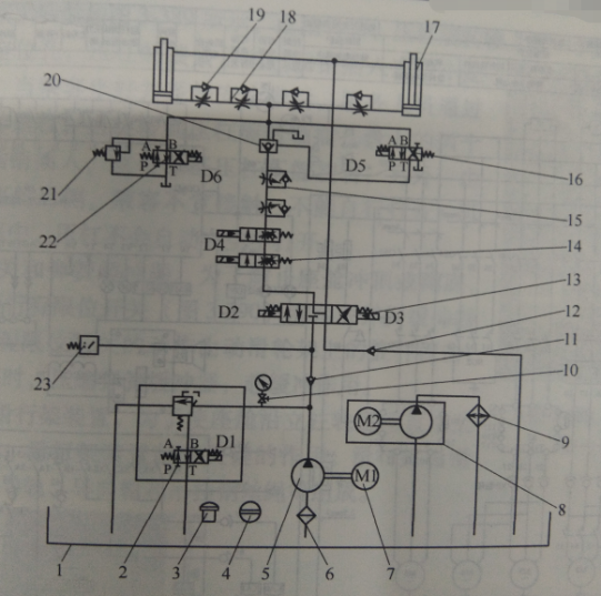
The working principle of the hydraulic system of the Hurricane Flying Chair
1-Tank 2-Solenoid relief valve 3-Filter 4-Level gauge 5-Low noise vane pump 6-Oil filter 7-Electric motor 8-Gear pump 9-Air cooler 10-Pressure gauges and switches 11. 12-One-way valve 13-Electro-hydraulic reversing valve 14-Solenoid throttle valve 15-Control Valve 16-The electromagnetic valve 17-Hydraulic cylinder 18-Pipe type one-way throttle valve 19-Plate check valve 20-Hydraulic check valve 21-Safety valve 22-Pressure Switch
①Oil level control. The oil tank is equipped with a liquid level gauge for visual inspection of the hydraulic oil level of the oil tank.
②Oil temperature monitoring. The oil tank is equipped with an oil temperature gauge, and the oil tank is equipped with a tubular electric heating element for low temperature heating, and the oil temperature cooling is forced to cool through the system oil return, and then control the heater to heat at low temperature and alarm at high temperature.
③Pressure and flow control.The system controls the pressure through the relief valve to strengthen the system protection; adjusts the system flow through the hydraulic pump; adjusts the lifting speed through the speed regulating valve.The system has two hydraulic cylinders to lift, maintain pressure and lower synchronously, thus effectively realizing the vertical running of the tower body along the track.
3)Electrical control principle:After pressing the ready button, the device rotates at a low speed to check the passenger’s seating condition.The hydraulic system starts to work when the equipment started. Laterly, the motor on the top of the tower drives the umbrella-shaped turntable to rotate, and then the middle turntable starts to rotate in dislocation. At the same time, the middle turntable starts to lift. The equipment enters the overall operation stage. The top motor starts to decelerate, and later, the middle turntable stops rotating, and at the same time, the middle turntable also starts to descend slowly, the whole machine realizes a smooth stop under the program control, and a working cycle is completed after the equipment is completely stopped.
The electrical control principle of the Hurricane Flying Chair
(3)The safety lever, upper limit and lower limit switch of the safety device seat are the main safety devices of the rotating flying chair. The function of the blocking lever is to prevent the passengers from being thrown out of the seat during operation, and a suspension chain for the pocket gear is also added under the blocking rod. slipped out of the gap.The upper and lower limits mainly prevent the lifting mechanism from rushing to the top or squatting to the bottom during the lifting process.

