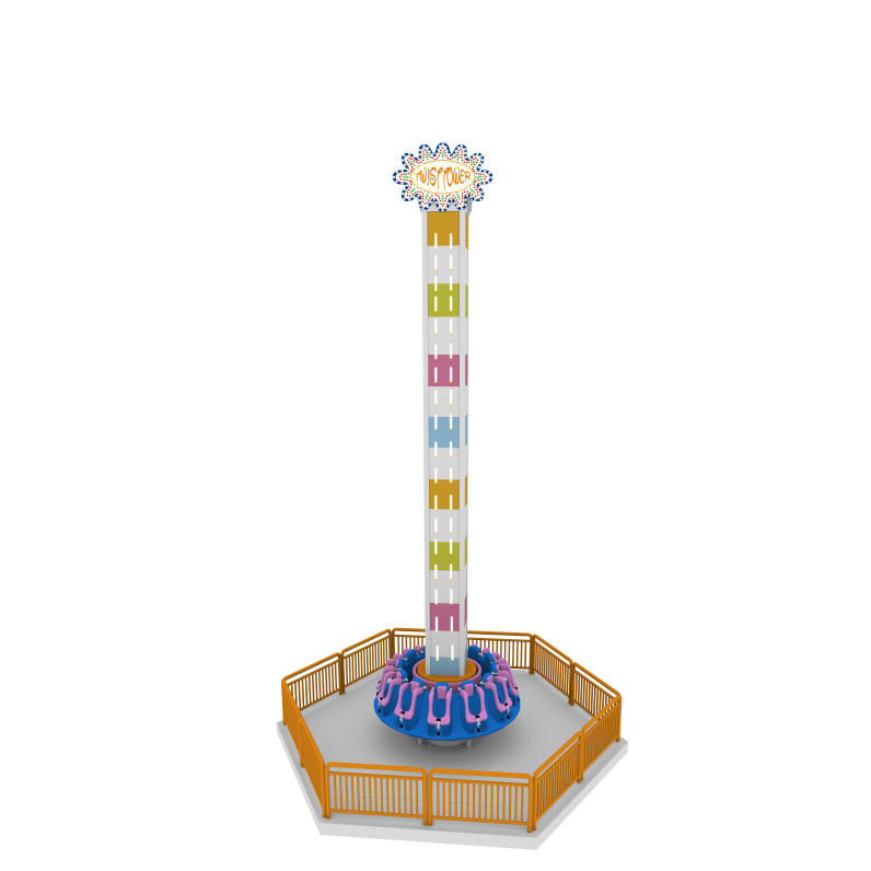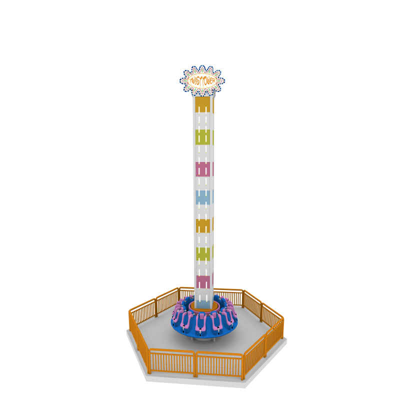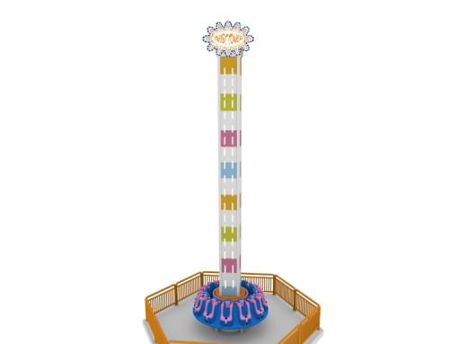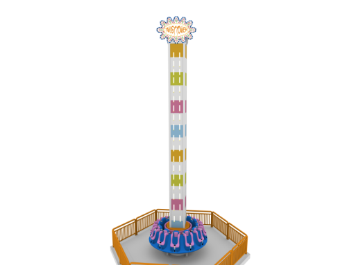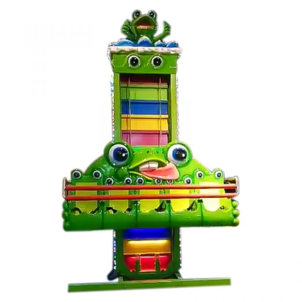
Parameter
Area:3.5X3.5m
Machine Height:3.7m
Capacity:5 persons
Power supply:380v
Power:8kw
Run Height:1.7m
Speed:1.2m/s
Weight:1.5T
Application range:amusement park、playground、theme park.
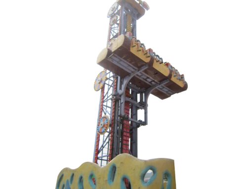
Frog Jump Series
The typical equipment of the frog jump series is the frog jump amusement machine. It is a new type of amusement equipment based on the frog jumping method, which makes tourists feel the fun of frog flying and jumping. It will make people with a feeling of suddenly going straight to the cloudy night, suddenly weightless, and approaching the height of excitement. After the operator sits down and fastens the seat belt and safety lever, the operator can start the equipment, and the tourist can quickly rise to a considerable height within a few seconds, and then shake down, shake up, and have a lot of fun.
1.The main structure.The main structure of the green baby dance is composed of electrical system, hydraulic system, mechanical system and auxiliary facilities. The mechanical system includes a cockpit, a sliding frame, a column, a base, a pulley block, and a safety pressure bar. The hydraulic system is the main power and composition of the lifting mechanism. When the cockpit is in the lowest position, the hydraulic cylinder is in a jacking state; when the cockpit is raised, the hydraulic cylinder is in a retracting state.
(1).Cockpit. The structure of the frog jumping cockpit is shown in Figure 1. In addition to the cockpit body, it also has pulleys, wire ropes, connecting pins, columns, buffers and safety devices. The actual cockpit is shown in Figure 2. The cockpit is made of glass fiber reinforced plastic and has metal structural brackets, seat belts and safety bars.
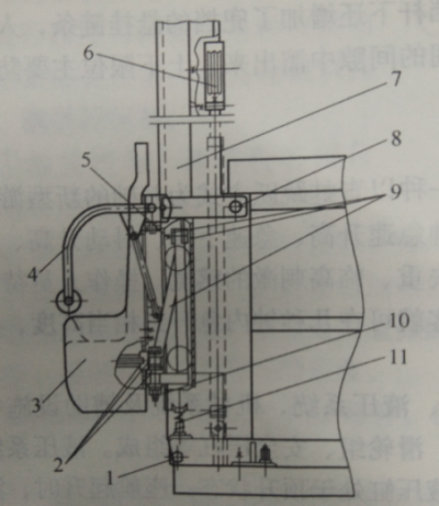
Figure 1 The structure of the frog jumping cockpit
1.8- Column pin 2- Cabin bracket and cockpit connection 3- Cabin 4- Safety pressure bar 5- Wire rope and cockpit connecting pin 6- Moving pulley 7- Column 9- Support rod 10- Connecting main shaft 11- Buffer
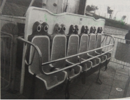
Figure 2 Frog jumping cockpit
The cabin safety locking device is shown in Figure 3. As it can be seen from the figure, there is a pin hole plate on the rotating shaft of the pressure bar, and there are two positioning holes for locking on the plate. The locking of the pressure bar is realized by inserting the bolt into the two positioning holes. After the passenger seated and the seat belt is fastened, the staff will pulls out the latch, rotates the pressure bar, and they will inserts the latch to ensure that the pressure bar cannot be rotate when it rotates to the two positioning holes on the revolving shaft socket plate of the pressure bar; In addition, it is not suitable for passengers to touch it and cannot be opened by itself as the device is installed on the rear side of the cockpit, which will ensures the pressure bar will not automatically open in the air during operation.
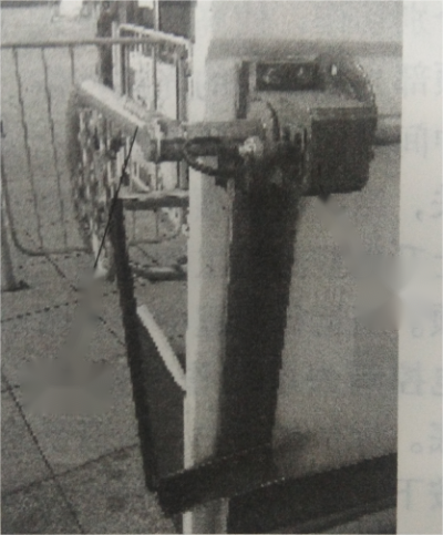
Figure 3 Frog Jump Cockpit
Safety locking device
2).Travel switch and spring buffer. In order to prevent the cockpit from topping out or squatting, a top-up travel limit switch (Fig. 4) and a squat bottom spring buffer (Fig. 4) will be seted respectively .
3).Track and carriage device. In order to make the cockpit rise, descend and jump vertically along the column track, the skid frame device plays a key role. The sliding frame is composed of sliding guide frame, channel steel guide rail, guide wheel and hanging wire rope.

Figure 4 Frog jump travel switch
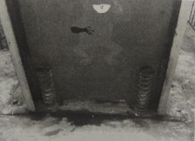
Figure 4Frog jumping spring buffer
The sliding guide frame is guided by 4 guide wheels and runs up and down along the vertical channel steel guide rail. In order to prevent wheel wear and the cockpit from swinging too much from side to side, a proper clearance should be maintained between each guide wheel and the track, which can be achieved by adjusting the adjusting bolts.The connection between the hanging wire rope and the guide frame is more important, and the connecting pin shaft bears a large force, so it should be checked regularly, and if it is worn, it should be updated in time.
2.Working principle. The frog jumping amusement machine is a kind of equipment that is electrically controlled by the cockpit to ascend, descend and jump along the column track. Therefore, its working principle is introduced from two aspects of mechanical transmission and electrical control.
1).Mechanical transmission principle: The ascending, descending and jumping movements of the passenger cabin and the sliding frame along the column track are obtained by the reciprocating hydraulic cylinder of the hydraulic system to drive the wire rope to enlarge the stroke through the pulley block, and the action of the hydraulic cylinder is the hydraulic system. The execution result of the setting program for the electrical control system. The working principle of the hydraulic system is shown in Figure 5.
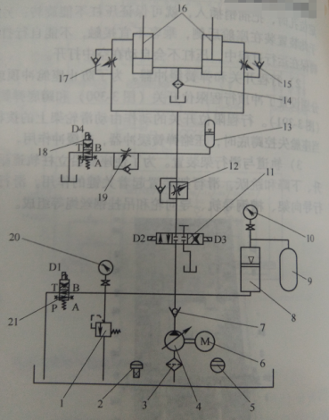
Figure 5 Working principle of frog jump hydraulic system
1- Relief valve 2- Filling port 3, 14- Oil filter 4- Hydraulic pump 5- Level gauge 6- Motor 7- Check valve 8, 13- Accumulator 9- Air storage tank 10, 20- Pressure Meters and switches 11-Solenoid valve 12-One-way speed regulating valve 15, 17- Falling speed one-way throttle valve 16-Hydraulic cylinder 18- Power failure descending valve 19-Superimposed one-way throttle valve 21-Unloading solenoid valve
2).Electrical control principle:The working process of frog jumping is controlled by the single-chip microcomputer on the circuit board of the sub-control box.
The sound and switch signal are used to control the 12V DC intermediate relay, so that the corresponding 220V electric control valve and hydraulic pump motor are powered and act according to the preset program.
The hydraulic pump motor runs to generate oil pressure when the equipment started, and the corresponding electronically controlled hydraulic valve is actuated separately under the control of the program, so that the high-pressure oil flows into (or flows out) the hydraulic cylinder to raise or lower the traction cabin.
When the cabin goes up, it shoots to the top. The light of the photosensitive device is blocked, and the photoelectric device outputs a low-voltage electrical signal, so the CPU outputs a bell signal, and drives the intermediate relay at the same time, so that the rising electric control valve stops falling and the electric control valve opens, and the cockpit descends.
3).Safety devices. The main safety devices include seat belts, safety pressure bars, travel limiting devices and buffers.
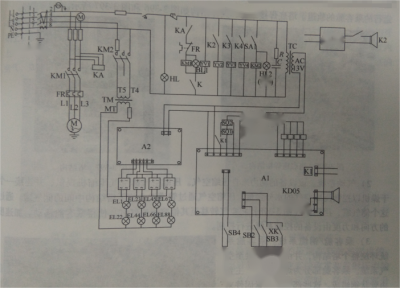
Figure 7 Frog jumping electrical control principle
Sounding shuttle series
The sounding shuttle is the most representative amost the sounding shuttle series. It is a high-tech amusement equipment developed at the end of the 20th century that integrates mechanical, hydraulic, computer and network technologies. Some people call it an upright “roller coaster”.
The international amusement industry calls it the amusement equipment that challenges the limits of human beings in the 21st century. After passengers get on the equipment, the cockpit is powered by compressed air, and is ejected to an altitude of about 40m along the vertical track at a speed of more than 20m/s, and then falls down in a free fall, and then ejects upwards again, and so on for two cycles.
After the second, the cockpit slowly descended to the platform by the orderly release of compressed air. This is a very exciting amusement equipment. People use “sounding shuttle” to describe the feeling of passengers flying into space in a spacecraft like astronauts.
Although this is not exactly the same as a real space launch, passengers can initially get the feeling of astronauts lifting off from it, which is really hard to forget.
On the other hand, the equipment can make the passengers directly feel many physical concepts, such as the conversion of electrical energy, compressed air potential energy and mechanical energy, overcoming gravity, positive and negative acceleration, free fall and weightlessness, etc., making the knowledge in books more intuitive , to understand more deeply.
1).Main Structure. The main structure of the “Sounding Shuttle” consists of a stand, a lift car (Figure 8), a cylinder, an air storage tank, an air compressor, an air dryer, a lubrication system, a control system and a lighting system.The vertical frame is a tower structure welded by square tubes.
There is a maintenance ladder on it. The lift truck is equipped with guide wheels. The guide wheels run along the outer side of the four square tube guide rails on the vertical frame. The lift is guided by the guide wheels. Run up and down the track. The guiding mechanism of the sounding shuttle is shown in Figure 9.
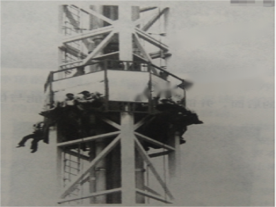
Figure 8 Sounding shuttle stand and lift car

Figure 9 The guiding mechanism of the sounding shuttle
Tower structure. The tower is a well-designed square tube welded structure, fixed vertically on steel embedded parts on a concrete foundation. The tower is capable of supporting all equipment and components except the compressor/dryer system and equipment control center, and can withstand the effects of wind loads and seismic events. It is designed to withstand wind loads and earthquakes. The vertical square tube acts as a rail for the passenger compartment that runs up and down. The welding structure and specific structure of the tower bottom are shown in Figure 10 and Figure 11.
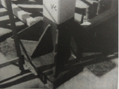
Figure 10 Welding structure of tower base
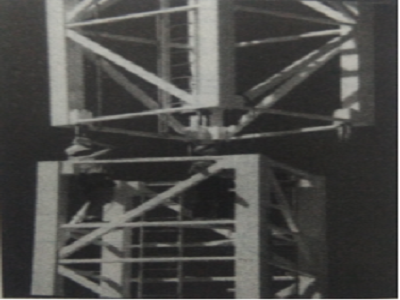
Figure 11 Tower structure
2)Pneumatic system. The device is powered by compressed air. Compressed air is supplied by an air compressor and connected to a dryer to control the moisture content of the compressed air. Compressed air is piped into an air tank located in the middle of the tower structure. Through this air tank, a gate valve (Figure12) is used to divert air to other containers or cylinders that move the passenger compartment. The direction and force of the acceleration is controlled by the device’s control system.
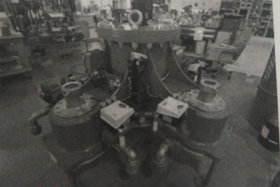
Figure 12 Valve gate
3).Passenger compartment/steel cable system. The passenger cabin system surrounds the entire tower structure and is connected to the air system by steel cables. The passenger compartment section is a welded assembly and consists mainly of tubular steel. These parts are connected using fasteners.
The wheels align the car to the tower and provide soft suspension as the car travels up and down the tower supports. Use fasteners to secure a single safety bar (Figure 13) to the carriage.
Route the wiring along the back of the car to ensure proper use of the lever snap lock and release function, as well as other functions such as restricted area monitoring.
The UHMW skid (Figure 3-14) ensures alignment of the passenger compartment in the event of tire failure. The brake pads for the passenger compartment are mounted behind the seats and can be adjusted so that they engage the caliper brakes located at the top of the tower, as shown in Figure 3-401.

Figure 13 Passenger safety bar

UHMW Figure 14 Tires and UHMW slides
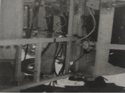
Figure 15 The rear of the passenger compartment
A steel cable system connects the passenger compartment to the air system. A complete cable loop exists on each side of the tower, so four cable loops ensure that the passenger compartment is connected to the tower’s air system.
Steel cables are installed on each safety cutout at the rear of the four main bodies of the carriage. Using the turnbuckle, stretch the cable evenly. Steel cables run in the direction of the pulleys at the bottom and top of the tower and are attached to the pistons that move up and down in each cylinder.
Special wire cable end caps located on the top and bottom of the cylinder help and restrict the air entering the cylinder, as shown in Figure 17.
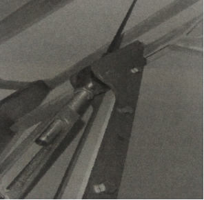
Figure 17 Cable/carriage interface
Working principle. The operation process of the “Sounding Shuttle” amusement machine is completed by the compression and release of gas. After the air is compressed by the compressor and dried by the dryer, it is fed into the air storage tank.
When the computer completes the calculation of the weighing of the passengers and the launch pressure, the compressed air in the air storage tank will inflate the launch tank according to the calculated value.
When the rated value is reached, the open passenger lift truck will be ejected to an altitude of about 40m along a 50m-high vertical frame within 2~3s; According to the program set by the computer, through the orderly release of compressed air, it completes free fall, oscillation, slow descent, and finally returns to the platform smoothly.
Safety equipment. The safety device of the equipment can be divided into two parts: air pressure protection device and passenger safety device.
1).Air pressure protection device: The air compressor is equipped with an over-pressure protection device, and the air storage tank and the launch tank also have an over-pressure protection device.
The over-pressure protection of the air pressure and the design of the cylinder piston stroke prevent the possibility of the lift truck hitting the roof; The orderly release of compressed air according to the computer program and the 4 sets of gas-liquid buffers at the bottom of the stand (see Figure 18) can prevent the fall of the lift car, and it can only be an orderly soft landing.

Figure 18 Sounding shuttle gas-liquid buffer
2)Passenger Safety Devices:Hydraulic safety bars and aviation safety belts are installed on the passenger seat, as shown in Figure 19.
The locking and unlocking of the safety lever can only be controlled by the operator. Generally, there should be two sets of independent locking devices, as shown in Figure 20.
In order to prevent the failure of the hydraulic safety pressure bar, two sets of aviation safety belts are also added: one set is fastened to the passenger, and the two ends of the other set are respectively fixed on the safety pressure bar and the embedded structure at the lower end of the seat.
Effectively prevent the failure of the safety lever locking. The failure of the safety lever is generally caused by the oil leakage of the hydraulic system, which causes its idle stroke to be too large. In addition, the controller of the PLC control system has the function of automatic detection of the equipment.
Once a certain link of the equipment is abnormal, it will stop the operation of the equipment. Only after the fault is eliminated, the equipment can work normally, which fundamentally ensures the reliability and safety of the equipment. Its touch-screen operating system makes operating the device easier and more intuitive.

Figure 19 Sounding shuttle safety pressure bar
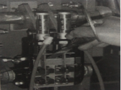
Figure 20 Locking device
3).Brake Assembly: Adjust the carriage brake pads to the center position. The brakes should lock when the upper carriage stop just engages the bumper. The bolted connections of the brake pads should be inspected for excessive wear, especially the smaller bolts holding the moving pads, as shown in Figure 21.

Figure 21 Brake Assembly


